

Clear records
history record

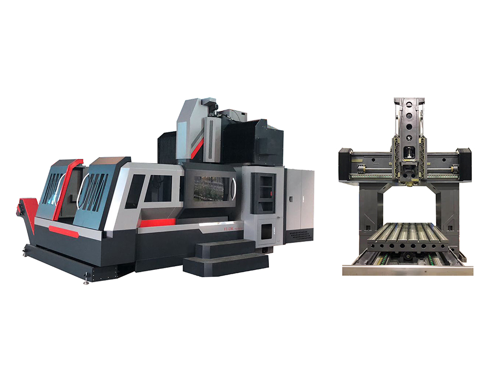
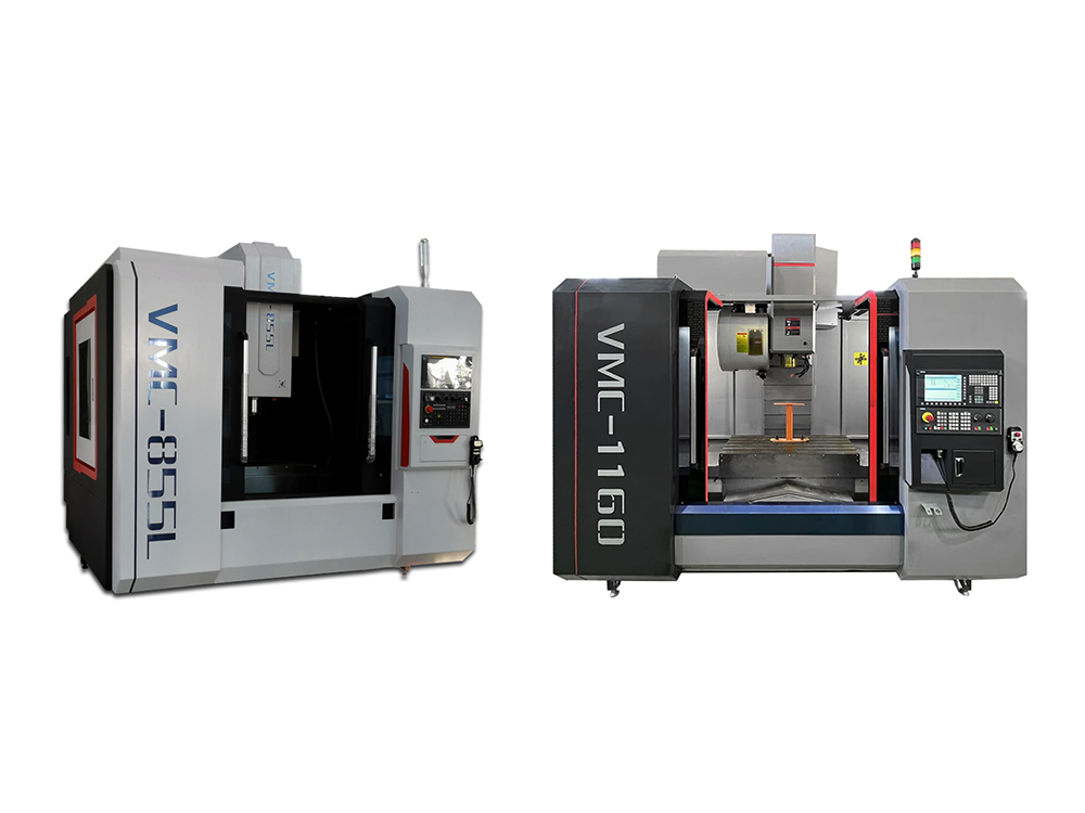
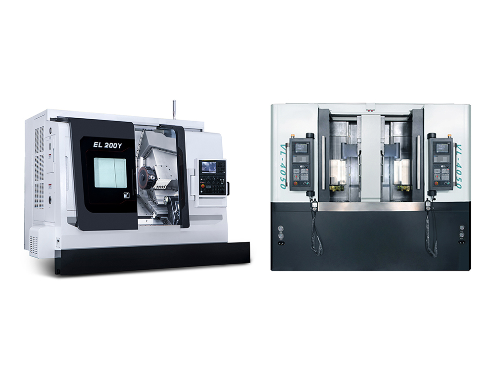
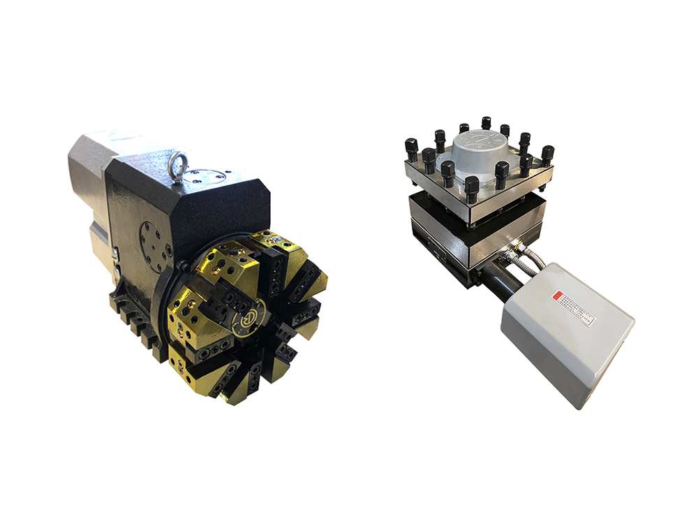
PRODUCT

RELATED PRODUCT


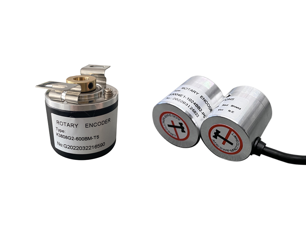
OPTICAL ENCODER MODULE


RS91 series is high performance, low cost, optical three-channel incremental encoder module.
The precision grating phase matrix receiving chip and light source are integrated internally, and the module can sense the position information and speed information of rotation with the code disk.
RS91 series of CPR according to the optical centre 11 standards are:100,200,256,360,400,500,512,600,1000,1024,2000,2048,5000.
FEATURES
▶ 1.Photoelectric matrix arrangement technology
▶ 2.Operating temperature -40°C- +105°C
▶ 3.Variety of CPR can optical
▶ 4.C type,easy to use
▶ 5.Output TTL Compatibility
▶ 6.5V supply
APPLICATIONS
Typical application package scraping printer, plotter, servomotor, factory automation,etc.
Maximum using environment
Storage temperature | Ts | -40°C- +105°C |
Working tempearture | Ta | -40°C- +105°C |
Power supply | Vcc | -0.5V-7V |
Welding temperature | not exceed 260°C/5 seconds | |
Working frequency | f | 500KHz |
Reverse voltage of light sourse | Vr | 3V |
RECOMMENDED ENVIRONMENT
Working tempearture | Ta | -40°C- +105°C |
Power supply | Vcc ripple voltage <100 mV | 4.5V-5.5V |
ELECTRICAL PARAMETERS
Electrical parameters are measured in 25°C recommended environment
Parameters | Symbol | Min. | Typical | Max. | Unit | Conditions |
Forward voltage of light source | Vf | 1.8 | 2 | 2.1 | V | If=20mA |
Module operating current | Icc | 40 | 50 | 60 | mA | |
Accept the working current of the chip | Icc | 36 | 42 | mA | ||
Output low level | Vol | 0.4 | 0.5 | V | Internal 2k ohm pull up resistor | |
Output High Level | Voh | 4 | 4.5 | V | Internal 2k ohm pull up resistor | |
A/B/Z Rise Time | Tr | 160 | ns | internal 2 k ohmic pull up resistance CL=8 PF | ||
A/B/Z Lower Rise Time | Tf | 20 | ns | internal 2 k ohmic pull up resistance CL=8 PF | ||
AB duty cycle | Dt | 40 | 50 | 60 | % | |
AB phase difference | θ | 60 | 90 | 120 | °e | |
Response frequency | f | 500 | KHz |
WAVEFORM DIAGRAM
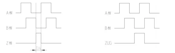
Figure 1 Output waveform of clockwise rotating A/B/Z (1/4T)1
Figure 2 Output waveform A/B/ZUG clockwise rotation
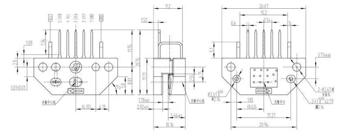
Module Mechanical Position Dimensions
PIN DEFINITION
PIN Name | Function | Input/Output |
Vcc | Power+, 5v | Power supply |
CH A | A channel output with 2K Ω pull resistance inside | Output |
CH B | B channel output with 2K Ω pull resistance inside | Output |
GND | Power ground | Power ground |
CH I (Z channel) | Zero bit Z signal output with pull-up resistance 2 Ω | Output |
NOTE:
▶ 1.The Z channel output has two choices, one is 1/4 T output, the other is zero bit original signal - ZUG output, ZUG output is about 1T, ZUG and A,B have no specified position relationship, but each device position is determined.
▶ 2.The zero bit output has the last bit of the model to select 1/4 T or the ZUG, The last digit is 1 means that the output of Z is Zug, the last digit 4 means that the output of Z is 1/4 T.
MODULE SELECTION GUIDE
RS91 series has a variety of options, according to the optical radius (ROP)=11 specific CPR selected as follows.
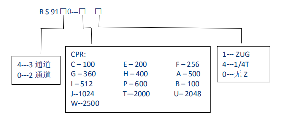
Attention: for other CPR, please contact us.
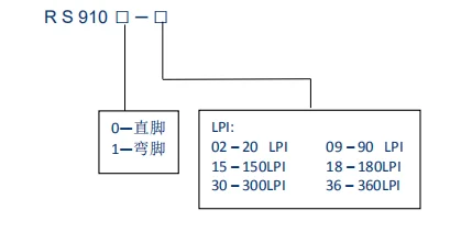
RS91 series of straight pin are named by LPI, as follows:

Contact Us
![]() Tel: (86 510) 68088084
Tel: (86 510) 68088084
![]() Whatsapp: +86-15852791610
Whatsapp: +86-15852791610
![]() Mailbox: info@wxfagor.com
Mailbox: info@wxfagor.com
